MIG welding settings
Unless you weld for a living, it is often difficult to know if your MIG welder is set up for optimal performance. If you find yourself asking questions such as "am I using the proper voltage?” or “do I have too much or too little wire?” then this article is for you! We will touch on the basics of properly setting up your welder, and then look at what your weld bead is telling you.
Equipment
Good equipment makes MIG welding easier, while poor equipment can cost you dearly in frustration and weld quality. MIG welders such as the Millermatic® 211 and Millermatic 141 are ideal for the occasional welder. If, however, you’re looking for a machine with multiple welding capabilities, we recommend multiprocess welders like the Multimatic® 215 and Multi
matic 220 AC/DC.
Some welding machines include technology advancements, such as Auto-Set™ technology, which sets optimal parameters automatically based on material thickness and wire diameter. This allows you to focus on proper technique.
To determine which welding machine best fits your needs, watch Which Welder is Right for Your Home or Shop or download this guide.
Getting the most from your machine
Regardless of your machine choice, read your owner's manual. It contains important information about proper operation and safety guidelines. Most companies also offer their manuals online.
The following basic MIG welding settings are for welding steel with solid wire. Joint design, position and other factors affect results and settings. When good results are achieved, record the parameters.
- Material thickness determines amperage. As a guideline, each .001 inch of material thickness requires 1 amp of output: .125 inch = 125 amps.
- Select proper wire size according to amperage. Since you don't want to change wire, select one for your most commonly used thicknesses.
• 30-130 amps: .023 inch
• 40-145 amps: .030 inch
• 50-180 amps: .035 inch
• 75-250 amps: .045 inch
- Set the voltage. Voltage determines height and width of the bead. If no chart, manual or specifications are available for setting the correct voltage, you can try this: While one person welds on scrap metal, an assistant turns down the voltage until the arc starts stubbing into the workpiece. Then, start welding again and have an assistant increase the voltage until the arc becomes unstable and sloppy. A voltage midway between these two points provides a good starting point.
There is a relationship between arc voltage and arc length. A short arc decreases voltage and yields a narrow, ropey bead. On the other hand, a longer arc (more voltage) produces a flatter, wider bead. Too much arc length also introduces the possibility of undercut.
- Set the wire feed speed. Wire speed controls amperage as well as the amount of weld penetration. A speed that's too high can lead to burn-through. If a manual or weld specification sheet is not available, use the multipliers in the following chart to find a good starting point for wire feed speed. For example, for .030-inch wire, multiply by 2 inches per amp to find the wire feed speed in inches per minute (ipm).
|
For wire size
|
Multiply by
|
Ex. using 1/8 inch (125 amps)
|
|
.023 inch
|
3.5 inches per amp
|
3.5 x 125 = 437.5 ipm
|
|
.030 inch
|
2 inches per amp
|
2 x 125 = 250 ipm
|
|
.035 inch
|
1.6 inches per amp
|
1.6 x 125 = 200 ipm
|
|
.045 inch
|
1 inch per amp
|
1 x 125 = 125 ipm
|
Examining the beads
One way to check your MIG welding settings is by examining the weld bead. Its appearance indicates what needs to be adjusted.
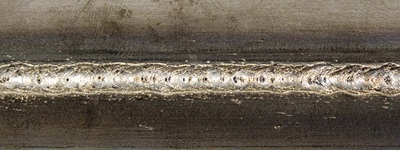
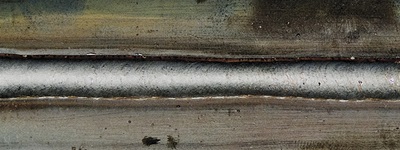
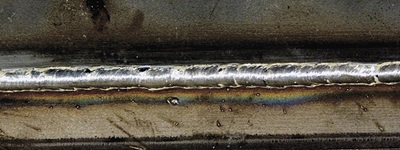
Good weld: Notice the good penetration into the base material, flat bead profile, appropriate bead width, and good tie-in at the toes of the weld (the edges where the weld metal meets the base metal).
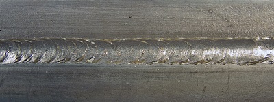
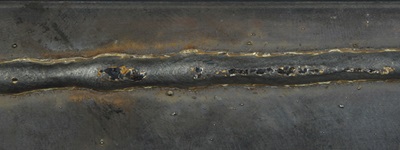
Voltage too high: Too much voltage is marked by poor arc control, inconsistent penetration and a turbulent weld pool that fails to consistently penetrate the base material.

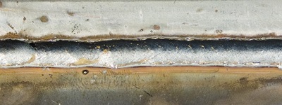
Voltage too low: Too little voltage results in poor arc starts, control and penetration. It also causes excessive spatter, a convex bead profile and poor tie-in at the toes of the weld.
Travel speed too fast: A narrow, convex bead with inadequate tie-in at the toes of the weld, insufficient penetration and an inconsistent weld bead are caused by traveling too fast.
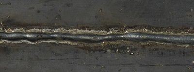
Travel speed too slow: Traveling too slow introduces too much heat into the weld, resulting in an excessively wide weld bead and poor penetration. On thinner material it may also cause burn-through.
Wire feed speed/amperage too high: Setting the wire feed speed or amperage too high (depending on what type of machine you're using) can cause poor arc starts, and lead to an excessively wide weld bead, burn-through, excessive spatter and poor penetration.
Wire feed speed/amperage too low: A narrow, oftentimes convex bead with poor tie-in at the toes of the weld marks insufficient amperage.
No shielding gas: A lack of or inadequate shielding gas is easily identified by the porosity and pinholes in the face and interior of the weld.