DIY ‘Thinking Stool’
I have a number of stools in my workshop, but I call my favorite the “thinking stool.” I usually do my best thinking when I’m sitting, and although my old wooden stool has served me well, it was getting pretty rickety, so I decided to make a stylish replacement from metal.
I chose round steel bar for the legs, with the footrests made from flat bar, and I decided to make the seat from steel sheet. The seat was the most time-consuming part, since I wanted to make it “fancy,” with a rounded edge and some bead-rolled details. Just for fun, I added a pattern of triangular holes to the top, creating an interesting design. I used the same height of the seat and footrest as on my favorite stool, which fits me perfectly. I look forward to many years of thinking (and working) while seated on this brand-new addition to my shop.
Scroll through the photos, and I’ll describe each step of the building process. The construction of the base is fairly simple, although the dimensions must be held carefully to keep the angle the same on all the legs and to keep the seat level. Getting all the sheet metal pieces for the seat properly fitted and smoothed was an exacting process, but I think it came out very well!
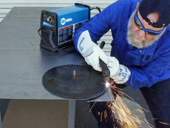
The seat is made from three pieces — the top, bottom and an edge band. I cut the blanks for the top and bottom from 19-gauge steel with my Miller® Spectrum® 375 plasma cutter, using simple patterns made from plywood. I also plasma cut the center out of the seat bottom to reduce the amount of unnecessary material. It is important to keep the torch body perpendicular to the work, and move with a consistent speed to get the best cut.
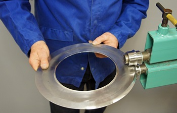
After sanding the edges, I used a beading machine with Rounding-Over dies to put a curl on each edge.
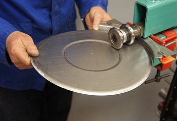
I used rounded step dies to add a design detail on both the seat top and bottom. The bottom step will match the perimeter of the ring, which will join the base to the seat.
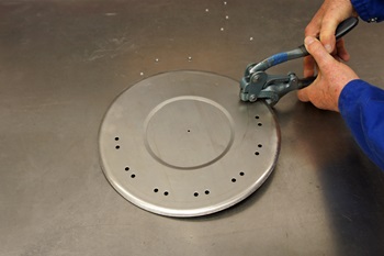
I’m using a hand punch here to make holes for locating the Jamey Jordan triangular punch and flare dies. These holes could be drilled, but punching is faster and cleaner.
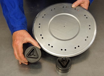
In the lower part of this photo, you can see the male and female portions of the triangular punch and flare tools, and the pins that align them.
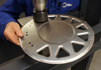
I’m using a hydraulic press here with the punch and flare dies. They do a beautiful job of adding a unique design to the seat top.
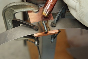
I cut a strip of metal 1-inch wide and rolled it into a circle to make the edge of the seat. The ends were joined with my Multimatic® 215.
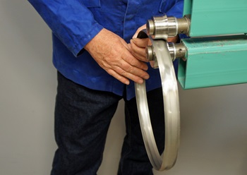
The weld is sanded flat, allowing the edges of the ring to be curled with the Rounding-Over dies in the beading machine.
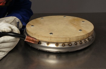
After all three pieces for the seat were formed, I tack welded them together. I temporarily attached a piece of plywood to the seat top to keep it perfectly flat while it was being fitted to the edge band.
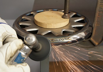
After tack welding, the joints were meticulously aligned with some careful hammering, and then finish welded together, using .023-inch diameter ER 70-S6 filler wire to keep the welds small. Here I’m sanding the weld flush with the base metal, using a 50-grit abrasive disc on a right-angle pneumatic sander.
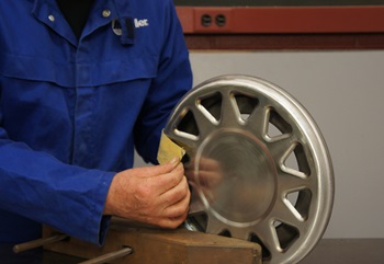
This is how the part looks with the welded areas sanded perfectly smooth. While it would certainly be possible to use plastic auto-body filler to smooth any irregularities, this part came out so well that no filler was needed.
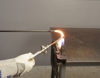
I used 1/2-inch-diameter cold-rolled steel round bar for the legs. Hot-rolled bar could be used, but it requires more cleanup before painting. I’m using a Miller oxy-acetylene torch with a multi-orifice heating tip to make the bend in each leg.
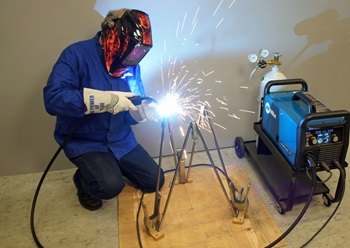
I cut each leg slightly longer than needed, then trimmed the top ends to a consistent length after bending. Next, I made a careful layout on a piece of plywood to position the bottoms of each leg 120 degrees apart and spaced an equal distance from the center point. Then, by aligning the tops of each leg segment, I automatically got an arrangement that positioned the legs at the same angle and made the seat base level. This fixture greatly simplified the alignment of the legs.
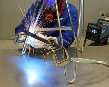
Next, I made the footrests from 3/16 x 3/4-inch stock. I cut them to the proper length, matching the angle of the legs. I clamped the footrests into place, making sure that each element was level and a consistent distance from the ground. Once they were properly fitted, I tack welded each footrest into place.
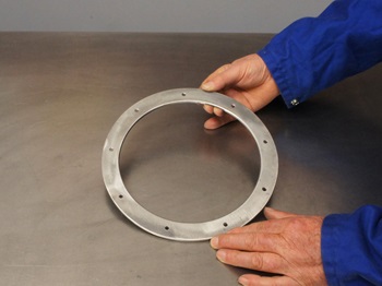
I plasma cut a ring from 3/16-inch steel plate and sanded the edges smooth. This joins the tops of the legs and provides the attachment of the base to the sheet metal seat. I drilled holes in the ring for the #10 machine screws, which will fasten the seat to the base. I later countersunk these holes, so I could use flat-head screws.
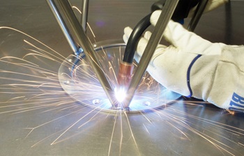
Here I’m tack welding the legs to the ring. After double-checking all the angles and dimensions, I finish welded all the elements of the base. On joints like this, where the parts meet at an angle, the gun is positioned to keep the angle the same between both elements.
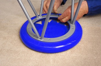
After painting, the legs and seat were joined with #10 flat-head screws, which fit flush, giving a very clean look.
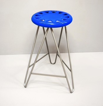
And here is the finished stool — ready for many years of thinking and working.
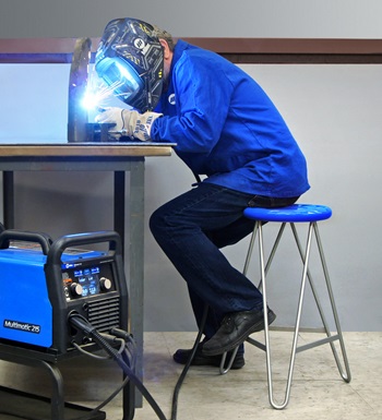
Extra photo of the stool, in use.
About Ron Covell
Ron Covell is a talented welder and metalworker in the automotive industry. Covell is a contributor for Hot Rod Network, where he has a popular column titled, "Professor Hammer's Metalworking Tips." He also owns Covell Creative Metalworking, offers instructional metalworking DVDs and hosts workshops around the country.