Article
Getting Started With TIG Welding MIG vs TIG Welding Equipment and Process
Learn the key differences between MIG and TIG welding, how the process changes when switching to TIG and how the right equipment helps build confidence and control.
Andrew Pfaller
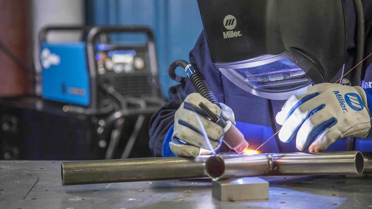
Gas tungsten arc welding (GTAW), or TIG, is often chosen for projects requiring high aesthetic quality, structural integrity or compliance with strict codes and standards. While TIG delivers precision, it is also the most difficult process to learn — which is why having precise control from equipment like the Miller® Dynasty® or Maxstar® series can make a difference in achieving consistent results. Follow these basic tips to prevent common TIG welding problems.
Insufficient shielding gas can lead to contamination and weak welds. This problem often occurs when the shielding gas is not turned on, the flow rate is set too low or too high, or airflow disrupts the gas coverage.
For more details, see TIG shielding gas best practices.
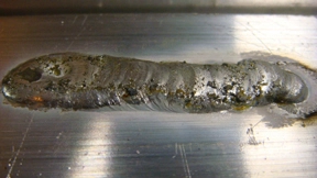
Figure 1: Poor gas coverage leads to contamination.
Using the wrong polarity when TIG welding aluminum leads to contamination. For example, welding on direct current electrode negative (DCEN) (see Figure 2A) fails to break down the aluminum oxide layer. The filler metal mixes in with the partially melted oxide, creating the contaminated bead seen here.
Always use alternating current (AC) for aluminum. AC polarity (see Figure 2B) combines two actions:
Adjust AC balance: A feature called AC balance control allows operators to tailor the EP to EN ratio. If you notice a brownish oxidation or flakes that look like black pepper in your weld puddle (Figure 2C), decrease the balance setting to increase the EP time for better cleaning. Caution: Too much EP causes the tungsten to ball excessively (Figure 2D) and could provide too much etching.
Start with a clean puddle: Wait until the puddle has the appearance of a shiny dot before adding filler. This indicates that the oxide has been removed and it is safe to add filler and move forward. Adding filler to the weld zone before removing the oxide layer results in contamination.
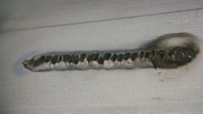
Figure 2A: Aluminum welded in DC with argon
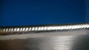
Figure 2B: Ideal aluminum weld
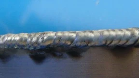
Figure 2C: AC balance set too high (insufficient oxide removal)
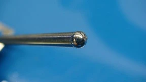
Figure 2D: Bald tungsten caused by a low balance setting (excess EP)
Improper fit-up or technique can cause incomplete fusion at the root — discover how to improve penetration. Several factors contribute to a lack of fusion at the root of a T-joint or a fillet weld.
Reduce arc length: Shorten the arc to maintain better directional control and improve penetration. This is especially important on transformer-based machines, where the arc tends to wander between the sides of the joint as it seeks the path of least resistance.
Avoid under-filling or rushing: Ensure proper deposition and maintain a steady travel speed to prevent incomplete fusion.
Use advanced controls when available: Inverter-based machines with advanced output controls such as adjustable frequency and pulsing — like Dynasty and Maxstar welders — offer more control over the arc. These settings create a narrower, more focused arc cone, providing deeper penetration and better directional control — often at higher travel speeds.
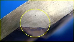
Figure 3: Lack of fusion in the root
Ending a weld too abruptly creates craters that can crack, such as the one shown in Figure 5A. Avoid with proper finishing techniques. Common issues include:
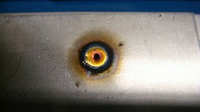
Figure 4A: Poorly filled weld craters
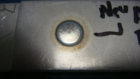
Figure 4B: Weld crater filled
Contaminated materials compromise TIG weld integrity — cleanliness is critical for strong, defect-free joints. Figure 5A shows the results of welding hot-rolled mild steel without removing mill scale first.
Figure 5B shows what happens when a weld on mild steel has been properly cleaned before welding. Figure 5C shows a weld made on uncleaned chromoly tubing, while Figure 5D shows a weld made on clean material.
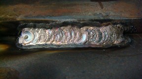
Figure 5A: Uncleaned steel weld
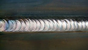
Figure 5B: Clean steel weld
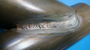
Figure 5C: Uncleaned chromoly
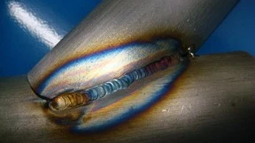
Figure 5D: Cleaned chromoly
Overheating stainless steel not only changes its color but also reduces corrosion resistance and weakens mechanical properties. Figure 7A shows discoloration caused by excessive heat input. Unfortunately, once this occurs, it cannot be reversed — prevention is the only solution.
Proper stainless coloration is shown in Figure 6B.
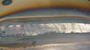
Figure 6A: Poor color on stainless steel
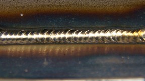
Figure 6B: Good color on stainless steel
Oxidation on the backside of stainless welds — known as sugaring — weakens the joint and compromises corrosion resistance. Figure 8 shows this common TIG welding problem, which occurs when the weld when it is exposed to oxygen during welding. The best way to prevent sugaring is to back purge the weld with argon shielding gas or reduce welding amperage.
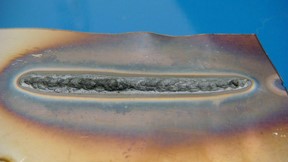
Figure 7: Sugaring on stainless steel
Excessive amperage can distort the weld and even cause burn-through. Figure 9 shows an aluminum weld with heat input set too high, resulting in a wide, ill-defined profile and poor bead appearance.
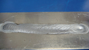
Figure 8: Excessive amperage/heat input
Maintaining a steady arc length is critical for consistent penetration and bead appearance. Figure 10 shows how an increase in arc length changes the weld bead color and profile. Arc length, which is the distance between the electrode and the base metal, directly affects TIG welding voltage and heat input.
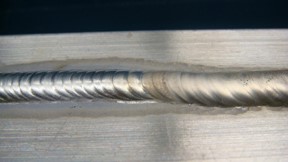
Figure 9: Change in arc length
Learn the key differences between MIG and TIG welding, how the process changes when switching to TIG and how the right equipment helps build confidence and control.
Learn the basics of TIG welding in motorsports applications and the proficiency of a TIG welder on aluminum and chrome-moly.