(As seen in Plant Engineering, June 2005)
Executive Summary:
- Difficulty moving heavy welders to the work site, such as downtime caused while waiting for a forklift, truck or crane to move the welder.
- Inability to bring a larger welder close to the job site while working in tight spaces.
- Difficulty finding useable primary power (e.g., only a 115 V outlet and you have a 230 V machine).
- Difficulty with primary power, such as voltage fluctuations, needing to add more welders but exceeding the capacity of the circuit, or facing additional assessed charges from the utility company for poor power factor (this bullet point applies to in-house personnel managing a fleet of welding equipment).
- Limited multiprocess welding capabilities, such as using one welder for Stick/TIG welding and another for MIG/flux cored welding.
- Problems with finding experienced welding personnel, or problems related to improper equipment set-up.
Inverter-based welders and plasma cutters can solve all of these problems because their advanced technology dramatically lowers machine weight and size, provides primary power management capabilities not possible with conventional welding technology and delivers unbeatable arc performance. Further, today’s inverter technology makes machines easier to operate. Their enhanced arc starts and arc performance can turn an average welder into a good welder, leading to improved weld quality and fewer rejects.
While not the focus of this article, conventional welding technology remains a good choice for many maintenance and repair applications. These welders can withstand severe abuse, work in harsh conditions and continue to function well for decades. Further, their limited mobility becomes an asset in some situations. When a welder needs to be left on a job site overnight, users can be confident that a 4,000-lb. multiple operator unit will still be there in the morning. Fig. 1 (below) provides some brief guidelines for selecting a welder for maintenance.
|
Conventional Welder
|
Inverter
|
|
Weight
|
·350+ lbs. for individual unit
·2,000 – 4,000 lbs. for multi-arc units
|
·10 – 120 lbs. for individual unit
·180 – 760 lbs. for multi-arc units
|
|
Input voltage range
|
208/230/460, etc. Requires manual relinking
|
115 – 230 or 230 – 575. Manual relinking not required
|
|
Single- or Three-phase
|
Fixed ability
|
Accepts both
|
|
Tolerance of voltage fluctuation
|
±10 % of primary
|
More tolerant¾See Auto-Line info
|
|
Power Factor
|
Poor – Good, depending on model
|
Excellent (up to .95; 1.0 is perfect). PFC inherent in design
|
|
Power Efficiency
|
Poor – Good, depending on age of unit
|
Excellent
|
|
Primary Current Draw
|
Traditionally higher
|
Traditionally lower
|
|
Multiple process arc quality
|
Fair – Good
|
Excellent
|
|
Enhanced arc control functions
|
Good
|
Good – Excellent
|
|
Durability
|
Excellent, generally more than 10 years
|
Good, generally up to 10 years
|
|
Reliability
|
Excellent
|
Fair – Excellent (varies by manufacturer)
|
|
Purchase price (cost per amp)
|
Generally lower
|
Generally higher
|
How Welders Work
All welders transform high voltage, low amperage primary power into the low voltage, high amperage power used for welding. The welder does this using a transformer, which is an iron core wrapped with hundreds turns of copper wire. Variables that determine the physical size of the transformer include the number of turns of wire, the cross-sectional area of the core, the voltage being applied and the frequency of the primary power.
The key variable—the one inverters address—is frequency. The equation that governs the design of a welder states that increasing the frequency of the primary power enables reducing size and mass of the transformer.
The secret of inverter technology is that it increases the frequency of the primary power reaching the transformer from 60 Hz up to 20,000 to 100,000 Hz. It does this through the on/off action of high power solid-state switches called IGBTs that turn on or off in as little as one millionth of a second. The on/off action simulates the building and collapsing of a magnetic field, which has a similar affect as AC power, but at a much higher frequency (see Fig. 2, a block diagram of an inverter, for more details).

By controlling power on the primary (or line side) of the transformer and boosting frequency, manufacturers of welding equipment now produce Stick/TIG inverters that weigh 10 to 50 lbs., all-in-one MIG welders that weigh less than 50 lbs. and multiple-process inverters (Stick/TIG/MIG/flux cored/gouging) that weigh about 80 lbs. and produce a 425-amp output. See Fig. 3 for a comparison of transformer size between a conventional welder and an inverter.
Fast ROI by Eliminating Wasted Time
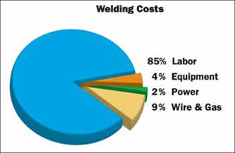
In an average welding operation, labor accounts for 85 percent of the costs (see Fig. 4, welding cost chart). Measuring how much a repair costs includes time spent to bring the welder and the work together, welding equipment set-up time, material preparation time, arc-on time, welding clean-up time (grinding spatter and slag or, even worse, costly rework), time spent moving the welder between jobs and time spent returning the welder to the tool crib, job box or storage space.
One contractor performing scheduled maintenance on a power plant calculated time saved to justify upgrading to inverter technology. Previously, the contactor used an eight-arc multiple operator system that weighed 4,000 lbs. By shifting to a “rack” system that holds and powers six arcs from one primary connection¾and weighs only 712 lbs.¾the contractor reduced labor time by 87 percent. In addition, with the welder close to the work, operators could easily adjust welding parameters or change processes.
Today, a four-arc rack for TIG/Stick welding can weigh as little as 180 lbs.—rack included— measure a mere 50 in. high, fit in an elevator and feature wheels for extreme mobility. Rack systems also offer the flexibility of removing individual welders from the rack. The individual inverters are little larger than a briefcase or carry-on suitcase (size varies by output power), so one or two people can easily move a small inverter and bring it into a tight space.
Primary Power Flexibility
Saving time by bringing lightweight inverters to the work does no good if you can’t find anywhere to plug it in. Inverter provides location flexibility through two types of primary power management technology: automatic linking technology and Auto-Line™ technology, which is available on some inverters from Miller Electric Mfg. Co.
With automatic linking technology, the inverter senses the type of primary power applied, then automatically (but mechanically) links to the correct power: 230 or 460 V, single- or three-phase, 50 or 60 Hz.
The Auto-Line circuit eliminates mechanical linking and uses electrical linking instead. The circuit boosts primary power to a higher voltage, and this power then becomes the source voltage for the inverter. The following types of inverters are available with Auto-Line (amperages are given at maximum output):
- 180-amp all-in-one MIG welder that accepts 115 through 230 V, single-phase only, 50 or 60 Hz
- 150-amp Stick/DC TIG units that accept 115 through 230 V, single-phase only, 50 or 60 Hz
- 200-amp Stick/DC TIG and AC/DC TIG/Stick units that accept 120 through 460 V, single- or three-phase, 50 or 60 Hz
- 425-amp CC/CV multiple process welders that accept 208 V through 575 V, single- or three-phase, 50 or 60 Hz
- “Multi-MIG” welders that accept 208 V through 575 V, single- or three-phase, 50 or 60 Hz (these units are specifically for high-volume production welding, not maintenance and repair)
- 55- and 80-amp plasma cutters that accept 208 V through 575 V, single- or three-phase, 50 or 60 Hz
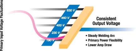
Note the emphasis on through. The primary power voltage can vary, but as long as it stays within the machine’s operating range, the power at the arc remains rock steady (see Fig. 5, Auto-Line circuit). Operators will never see a flicker, and the machine will operate continuously through conditions that cause other machines to shut down for self-protection or trip the circuit breaker. This benefit really pays off on sites with dirty power or when running off generator power. Note that to create a cost-efficient two-arc welding station in the field, some companies pair an engine-driven welding generator and use its generator power to run an inverter.
The availability of inverters with Auto-Line means that a person making welding repairs can move not just anywhere inside a plant, but can travel anywhere in the world without having to worry about finding available power.
More Power Per Pound, Less Current Draw
People encountering an inverter for the first time usually cannot believe that such a small machine provides so much welding output. For example, small Stick/TIG inverters weigh less than 14 lbs., but can have enough power to weld with a 1/8-in. Stick electrode. Even an inverter for carbon arc gouging with 3/8-in carbons at 600 amps weighs only about 120 lbs.
Inverters also provide outstanding power efficiency, which can lower utility bills, and they make good use of the primary power being supplied, which is known in the industry as good power factor. Good power factor lowers amperage draw, which may enable adding more welders to existing primary power. For example, one muffler manufacturer recently faced the dilemma of needing to increase production to meet demand, yet thought that it could not add to its fleet of 40+ arcs without making changes to incoming service—changes that may have cost up to $50,000.
Instead of adding more conventional 250-amp AC/DC TIG welders, which draw between 52 and 96 amps of primary power at rated output on 230 V primary, the company purchased 200-amp AC/DC TIG inverters, which draw less than 16 amps at rated output. The company added eight inverters, increased productivity and met demand without any changes to incoming service.
Mechanical contractors working in processing (petchem, paper, food) facilities and power plants also benefit from low primary power draw and primary power management. These job sites are often starved for power and may have generator power that fluctuates. An inverter’s low-amp draw means that a single generator can power more arcs and, as noted, features like Auto-Line enable an inverter to ride through voltage dips and spikes.
The Ultimate Welding Machine
By switching primary power at thousands of Hz and using advanced microprocessor control, an inverter can create optimum arc performance in any given welding mode. Thus, operators can weld at their best and not fight the arc, or they can select the welding process best suited for the job.
A brief review of inverter benefits in maintenance/repair applications include the following:
- Multiple process welding outputs. Models are available for Stick/DC TIG (for steel and stainless), DC TIG/Stick (these welders have more functions for controlling the TIG arc, such as pulsing and high frequency arc starts), AC/DC TIG/Stick (the AC output is necessary for welding aluminum) or a CC/CV output. The CC, or constant current output is used for Stick, DC TIG and gouging, while the CV output is used for MIG and flux cored welding. When a job requires both CC and CV processes, a CC/CV inverter means that there is one less machine to purchase or transport to the job site.
- Excellent arc starts. Weld flaws often occur during arc starts because the arc fails to establish itself quickly. Inverters typically provide more positive arc starting, which can help ensure a quality weld the first time, eliminating rework later. A single welding repair could cost hundreds or thousands of dollars, so eliminating a handful of weld flaws can pay for a new inverter.
- Dig control for Stick welding. Dig control prevents the electrode from sticking when the arc gets too short. This is helpful for an open-root pass or tight fit-up work and aids in arc initiation.
- Broad range of inductance control for MIG welding. This allows an operator to create a “softer” arc (more inductance) or “stiffer” arc. Add more inductance for better wet-out (especially on stainless) or to reduce spatter, which can save hours of post-weld grinding.
- Improved pulsed MIG or pulsed TIG output (ability to tailor the pulsed wave form). Depending on the application, pulsing can reduce heat input for less warping distortion or burn-through, improve bead aesthetics, reduce spatter, provide out-of-position puddle control and increase travel speed.
- Output frequency adjustment and extended balance control for AC TIG welding. These functions enable tailoring the weld bead profile to match the application to improve weld quality, minimize post-weld grinding and substantially increase travel speed.
- User-friendly controls. Functions such as last procedure recall remember preferences when changing the polarity, such as starting method and panel or remote control. To account for operator preferences, yet to keep operators out of trouble by making incorrect adjustments, some inverters have four-position controls simply labeled for “stiff” or “soft” arc characteristics with E6010 and E7018 Stick electrodes. Control panels are also color-coded by process, such as green for TIG, orange for Stick and blue for wire welding. Manufacturers also try to provide commonality among their equipment, so the control panel design on an inverter may resemble the control panel used on an engine-driven welding generator the operator used on a previous job.
In addition to user-friendly controls, manufacturers also address the need for user-friendly processes. The welding world generally acknowledges that wire welding (MIG or flux cored) is the easiest process to learn, with Stick being harder and TIG the most difficult (which is not to say Stick welding is easy!).
Nearly anyone with decent hand-eye coordination and the right attitude can become good at wire welding for general applications with a few hours of practice. However, wire welding for on-site repairs can be difficult. Even a small MIG welder that runs on 115 V power weighs 60 lbs., and the bottle of shielding gas often weighs more than the welder.
Miller addressed this situation by creating the world’s first entirely self-contained all-in-one MIG welder, the Millermatic® Passport™. This 45-lb. inverter (see Fig. 7) features a 12-oz. internal CO2 shielding gas bottle (actually a paint ball cylinder) that provides enough gas for 25 minutes of welding. For quick welding repair or light fabrication in the field, no other wire welder completes the job faster or easier.
If your job calls for bringing the welder to the work site, requires multiple process welding or you face challenges related to primary power management, then take a closer look at inverter technology. Saving 10 or 20 hours of time, a realistic goal on a single large job, means that a new inverter will pay for itself many times over within the two or three years typically allotted for capital investments. And
an inverter helps get a facility up and running in an emergency, it’s worth its weight in gold.
Fig. 7