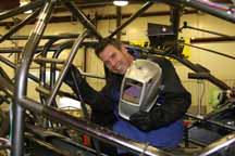
 Todd Bevis poses with one of the chrome-moly roll cages he built
By: Todd Bevis, Chassis Engineer, Cagnazzi Racing and Andy Weyenberg, Motorsports Coordinator, Miller Electric Mfg. Co.
Just as a NHRA (National Hot Rod Association) drag racing team depends on blend of team talent to win races, the material selected for a particular application requires a blend of properties to withstand the stresses involved. For a drag racing chassis, and for many other motorsports and aerospace applications, that material is 4130 chromium-molybdenum, or chrome-moly, which is selected for its blend of ductility, strength, weight and fabrication advantages.
The 4130 grade of chrome-moly is a high-strength low-alloy (HSLA) steel that contains molybdenum (0.15 - 0.25 percent by weight) and chromium (0.8 - 1.1 percent by weight) as strengthening agents. However, it has relatively low carbon content (nominally 0.30 percent), so it welds, machines and bends almost as easily as 1018 DOM mild steel tubing (which has an 0.18 percent carbon content).
Fig. 1—A comparison of 4130 chrome-moly to 1018 DOM tubing (cold drawn, normalized state)
| Material |
Tensile Strength |
Yield Strength
|
Hardness, Rockwell B |
Elongation |
4130 chrome-moly
|
97,200 psi
|
63,100 psi |
92
|
25.5% |
| 1018 DOM |
63,800 psi
|
53,700 psi
|
71
|
15% |
Chrome-moly is not lighter than steel, a common misconception. Both weigh about 491 lbs. per cubic foot. However, as Fig. 1 shows, chrome-moly offers a better strength-to-weight ratio and better elongation (a measure of ductility), which enables designers to use thinner wall and/or smaller diameter tubing to reduce overall weight.
Because many motorsports, aerospace and sporting goods applications involve welding normalized 4130 chrome-moly tubing with a wall thicknesses of < .125-in., this article will focus on best practices for these applications.
Welding Consumables and Variables
Fig. 2 summarizes the welding procedures, consumables and variables required for most tubing applications. The images and text that follow expand on this information to provide further clarification and guidance.
Fig. 2—Summary advice for welding 4130 chrome-moly
| Material |
4130 chrome-moly tubing (normalized). |
| Thickness |
< 0.125 in. Most chassis tubing has a wall thickness ranging from 0.035 – 0.083 in. and diameters from 1/4 - 1-5/8 in. |
| Amperage |
1 amp per .001 in. of wall thickness. |
| Polarity |
DC Electrode Negative. HF for arc starts only. |
| Pulsing |
Optional. |
Filler Material
|
ER70S-2 or ER80S-D2. |
Filler Diameter
|
0.030 – 1/8-in. Generally, do not use a rod larger than the thickness of the base metal. |
| Tungsten Type |
2% type (Ceriated is first choice, then Thoriated) |
Tungsten Diameter
|
1/16 – 3/32 (smaller diameter for thinner wall). |
| Tungsten Prep |
Pointed. |
Arc Length
|
Less than or equal to the electrode diameter. Generally, the tighter the better, as shorter arc lengths reduce heat input. |
| Electrode Stickout |
No further than the distance of the inside diameter of the cup being used. However using a gas lens can extend this distance. |
| Gas Lens |
Not required, but helpful if a tight joint configuration demands a longer stickout or involves multiple tubes. Keep the screen free of debris and spatter. |
| Shielding Gas |
100% argon, 15 – 20 CFH. More is not better, as turbulence could suck atmosphere into the weld. |
Pre-flow
|
.4 to .6 seconds. |
Post-flow
|
10 – 15 seconds. |
| Backing Gas |
Follow applicable codes/standards, if any; not required for NHRA applications. |
| Pre-heat |
Not required as long as tubing is above 60 – 70 degrees F. |
Stress Relief
|
Not required on material < 0.125 inch; simply allow the weld to air-cool. |
| Tack Welds |
Four tacks made 90 degrees apart; tacks ideally should be longer than wide. |
| Joint Preparation |
Tubing notcher for coping, drum sander for final fit-up, deburring for edge preparation, Scotch-Brite™ or 120 grit sand paper to clean about 1 in. back from the joint, and final clean with acetone, lacquer thinner or similar solvent to remove oil. |
Joint Gap
|
None! Realistically, gaps smaller than 0.010 are permissible; larger gaps promote poor quality. |
Weld Size
|
Keep welds to within their specified size: a weld needs to be no larger than its thinnest section, which will be the “weakest link” in the chain. Larger-than-necessary welds add excess heat and waste gas, filler rod and time. |
| Weld Technique |
Weld in one continuous motion, pulsing the foot control and adding filler rod to create the “stack of dimes” appearance (or use the machine’s pulsing controls). Do not stack separate puddles on top of each other, as this may lead to incomplete fusion. |
End-of-Weld Procedure |
Avoid pinholes by tapering off heat input at the end of the weld and maintaining a constant distance between the tungsten and the weldment. |
Weld Appearance
|
A good weld looks shiny and has a bluish tint. A dirty, gray-looking weld may indicate poor shielding gas coverage or excess heat.
|
Perfect Fit-Up
When welding thin-wall tubing, whether chrome-moly or other metals, the welders at Cagnazzi Racing joke that their tolerances range from perfect to almost not perfect. That is, if the parts don’t fit perfectly, they start over because thin-wall tubing does not have sufficient mass to absorb excess heat.
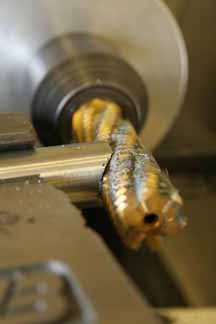
The usual “trick” to filling gaps with GTAW is to use a larger diameter filler rod. However, larger rods require more heat, and excess heat promotes burn-through, warping and embrittlement. Using a larger rod might be an acceptable solution in a non-critical application, but it’s a poor practice when welding chrome-moly. Fig. 3 shows an example of perfect fit-up, with the proper diameter filler rod shown for perspective.
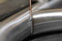 |
| Figure 3 |
Consistency
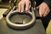
Cagnazzi uses hundreds of jigs and fixtures bolted to a surface that is flat to within a few thousandths of an inch for fabricating even the smallest items to help ensure tight fit-up and consistent tube placement, which provides repeatability (see Fig. 4).
| |
|
|
| |
Figure 4 |
|
By producing a new chassis nearly identical to the previous, the crew chief can hone his craft of gear ratio and clutch management without worrying about a new chassis introducing unknown variables. Many fabricators believe that they cannot afford to build fixtures for all of their components or for larger weldments. However, if repeatability and accuracy are important, good fixturing is mandatory.
Coping Mechanism
Most of Cagnazzi’s jigs have a go/no-go type fit, which enables “sneaking up” on a perfect fit by making small incremental adjustments.
 |
 |
| Figure 5 |
Figure 6 |
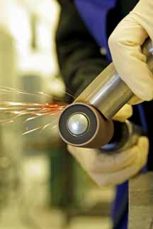
After cutting to approximate length with a band saw, Cagnazzi uses a tube notcher (Fig. 5) for rough coping. The fabricator will then check the length and use a drum sander to sneak up on a perfect fit by slowly sanding away excess metal from the mouth of the tube (Fig. 6). Before welding, the fabricator will deburr the edge (Fig. 7), clean back 1 in. from edge using Scotch-Brite or 120 grit sandpaper and remove oils or other contaminants with a solvent (Fig. 8). Be sure to wear nitrile gloves, as the natural oils from your fingers can ruin a weld just as thoroughly as grease or cutting fluid. Don’t forget to use the sandpaper and solvent on the filler rod, too.
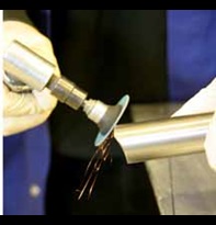 |
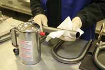
Figure 8 |
| Figure 7 |
|
Filler Metal Selection
In many motorsports and aerospace applications, engineers want some degree of ductility in the weld to help absorb impacts and prevent cracking. For this reason, most NHRA fabricators intentionally dilute the strength of the parent material by selecting ER70S-2 for filler for roll cages, chassis and other applications requiring more flexibility. While actual tensile strength of the weld will vary and depend on other factors, 4130 diluted with ER70S-2 filler likely produces a weld with a tensile strength in the 80,000 to 82,000 psi range.
For areas requiring higher strength, such as spindles and upper and lower control arms, fabricators select ER80S-D2 filler, which produces welds with a high tensile strength (as a side note, consider that S-2 fillers clean impurities better than D-2 fillers). In any event, do not use 4130 filler, as the weld will not have sufficient ductility unless it undergoes stress relief.
As for filler rod diameter, use a rod diameter that matches the thickness of the base metal. Trying to weld 0.035-in. tubing with a 1/16th inch filler (0.063-in.) is a bad idea because the tubing wall will melt before the filler rod is up to temperature. Cagnazzi predominantly uses 0.030-, 0.045- and 0.063-in. (1/16th) filler rods (Fig. 9), with .045 and .063 being the most common. For thicker, larger diameter tubing they use 3/32- and 1/8-in. rods.
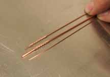 |
| Figure 9 |
Heat Control
Successfully welding 4130 requires preserving its mechanical properties by heating and cooling the weld in a controlled manner. Excess heat causes carbide precipitation, and cooling too quickly causes embrittlement. Fortunately, the GTAW process provides sufficient heat control. Welds made on tubing 1/8-inch or thinner do not require pre-heating or post-weld stress relief, yet they will have sufficient penetration as long operators follow the general rule of the thumb by using 1 amp per 0.001 in. of metal thickness. In Fig. 10, the operator prepares to weld thin wall tubing.
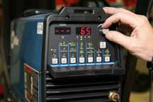 |
| Figure 10 |
Note that if the tubing is below 60 degrees F, use a small propone torch to heat the base metal to up to 300 degrees F. Otherwise, the metal could cool too quickly and become brittle. Welding cold metal may also promote hydrogen cracking, so that’s another reason to preheat 4130 if it’s cold.
Puddle Size and Arc Length
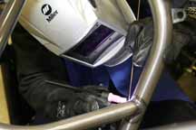
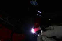
While welding too slowly increases overall heat input, operators should not necessarily focus on welding travel speed. Rather, they should focus on controlling their body (Fig. 11), controlling puddle size by making the puddle only as wide as necessary and holding a tight arc length of 1/8-in. or less (Fig. 12).
 |
 |
| Figure 11 |
Figure 12 |
Note that a longer arc length, or tungsten tip-to-work distance, increases overall heat input because a GTAW power source automatically increases voltage when arc length increases. If the joint configuration limits access because of cup size, do not try to weld with a longer arc. Rather, use a smaller cup or a gas lens and extend the tungsten.
To better control heat input, and to enable repositioning the body to better control torch movement, do not weld the circumference of a tube in one pass. Rather, weld it in four quarters. Weld only two of the quarters (on opposite side of the tube) then move to another joint. When the first joint cools, come back and complete the remaining sections.
No Slacking Allowed—Ever
The authors of this article weld 4130 tubing in critical applications, and they have a combined 50 years of welding experience. As such, they take every step of the fabrication process seriously. “Close enough” is simply not good enough for NHRA or aerospace work, nor should it be for even a child’s go-kart or bicycle. While professionals weld most chrome-moly tubing, the aspiring chassis fabricator or experimental aircraft enthusiast can weld it at home. In any circumstance, follow proper procedures and any applicable codes and standards.