Article
How to Set Up a Welding Space in Your Garage or Shop
From shop layout to must-have equipment, learn how you can create your own welding space.
Luke Merrill
A basic principle in welding is controlling heat input. See how Luke Merrill prevents welding distortion with proper heat control.
One of the basic principles of welding is heat control. Heat will affect any type of material that is welded or cut with any process, no matter what. How much the heat will affect the particular item you’re welding or cutting will vary based on the material type, thickness and shape as well as the welding process and the amount of heat (or amperage).
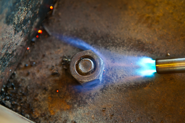
In general, heating and then rapidly cooling any material (as any welding process does) will cause shrinking. Shrinking is what you are attempting to minimize with proper heat control. You will never be able to eliminate shrinking from any welding process entirely because it happens on an atomic level; atoms react to temperature. A real-life example of heat causing an atomic level change is heating up a rusty nut: it will generally come off easier when it’s hot because it expands. When you weld, the area being welded will expand slightly because atoms are moving fast and colliding with each other. After you are done welding, the immensely hot weld rapidly cools and the atoms will actually experience “shock” and form back tighter than they were before the heat was applied, which will cause shrinking.
Think about this simplified hypothetical example. You’ve been inside your house for most of the day. It’s a comfortable 70 degrees inside. You’ve acclimated to that temperature and you’re in a totally relaxed state. Not stressed, not shrunk, just relaxed and happy. However, if you go outside into 100-degree blistering hot weather, you will be stressed and probably expand (just kidding, but you will be stressed). Spend an hour outside in that weather and then go back inside that same 70-degree house. You will be “shocked,” feel freezing cold and “shrink up” your body to try and conserve heat. While it’s not an exactly identical process, it is a good comparison of what happens on an atomic level to material being welded. The weld shrinks because it is shocked by a rapid temperature change.
Shrinking can only be counteracted in two ways:
Again, the amount of shrinking will depend on several factors, including the welding process used. For general light fabrication purposes, the most conventional processes used are MIG and TIG.
Each process has its own pros and cons. Some will argue that one is better than the other, but I will use either or both, depending on the application.
Side note: I think it’s worth briefly mentioning that gas welding, while not as commonly used, has many similarities to and the pros/cons of TIG welding, so keep that in mind.
PROS:
CONS:
PROS:
CONS:
So with the basic pros and cons listed for each welding process, which process and settings are the best for heat control? That is something that could be debated between every fabricator and welder for every different project. However, I am going to lay out what I have found works well for me on something I commonly do.
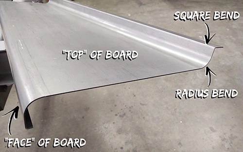
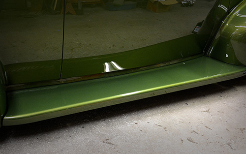
I build 16-gauge (0.063") steel running boards for 1930s–1940s cars and trucks. I utilize a combination of MIG, TIG and plasma processes when building these running boards. I start with a “blank,” which is a large piece of cold-rolled steel that has been preformed with one or more radius bends and one or more square bends on the edges.
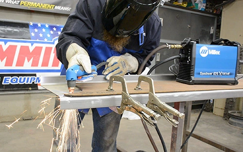
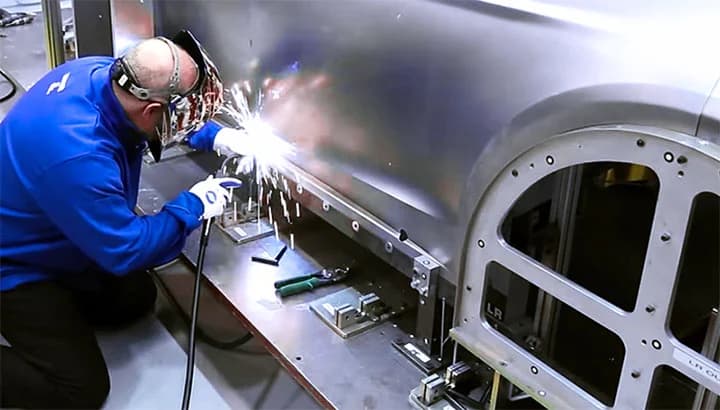
First, I cut the running board to mimic the factory shape of the OEM running board using the plasma cutting process and a wood template that I previously made. I use the Miller® Spectrum® 625 X-TREME™ for all of my plasma cutting (from 22 gauge all the way up to 5/8 inch). For personal protective equipment while plasma cutting, I use a Miller Shade 5 face shield, gloves, and a welding jacket.
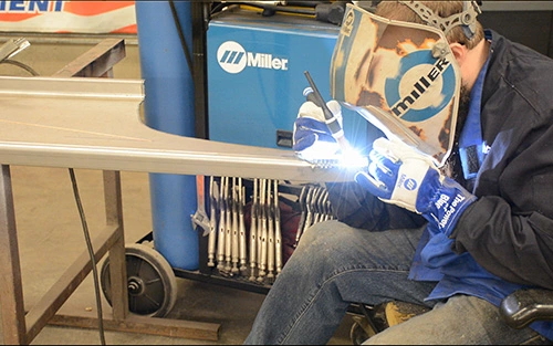
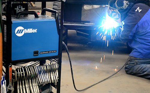
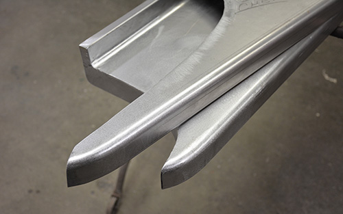
Many running board manufacturers stop with the simple forming and plasma cutting, with no further shaping or welding. One thing that distinguishes the running boards we produce is that we actually shape the ends so they flow and look better on the vehicle. That is where the two different welding processes come into play, and where I will discuss why I like to use the Miller Multimatic® 220 AC/DC and how MIG and TIG can both be used to their full advantage on this project. My favorite features of this machine are its size and the fact that I can set up both MIG and TIG processes in my work area with only one machine, sit down and never have to get up again to change machines when I switch welding processes. The QuickTech™ feature will automatically switch between each process as soon as you pull the trigger or press the pedal.
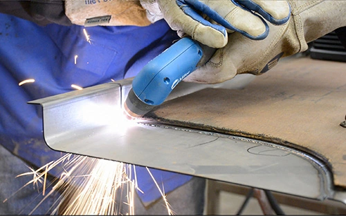
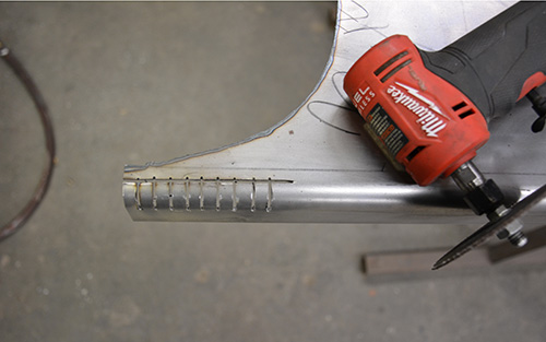
Now that the boards are cut and the welder is set up, I start working the radius formed edge. I begin by making a horizontal cut on the tangent point of the radius (where the flat meets the start of the radius). Next, I make vertical relief cuts using a 1/16-inch cutoff wheel on a grinder. These relief cuts allow me to hand form the end of the running board. I also cut the shape in the top of the board, removing a wedge of material from the top of the board. This is where the aforementioned relief-cut section will be shaped and welded to.
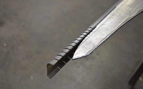
Once those cuts are made, I then relief-cut the bottom square edge. Cutting the square edge will facilitate me hammering the face of the board to the proper shape to match the top of the board without distorting anything. With some projects you can simply heat- or cool-shrink the lip or tuck-shrink the lip to get it to work, but for this project the easiest way is with relief cuts.
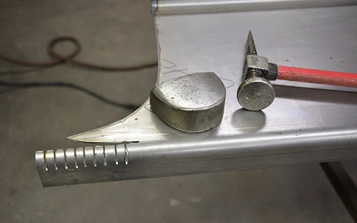
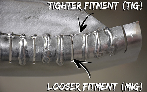
Next, I shape the end with a hammer and dolly. I then align and tack-weld the tops of the relief cuts to the top of the board using MIG welding. Using MIG here makes it easiest to align the metal properly because I can use one hand to hold a hammer or screwdriver, holding the metal tight to the shape, and then tack-weld using the other hand. I do very small tacks here, and I fit the seam on the top of the board as tight as possible. A tight-fitting seam will require the least amount of filler metal to weld, therefore causing the least amount of heat and shrinking.
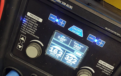
For this project, I typically use the “stock” MIG setting on the Multimatic for 16 gauge with .023-inch wire. The autoset values have always been fairly accurate for me in any non-overhead positions. If I am welding overhead, I raise the wire speed a little.
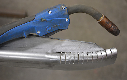
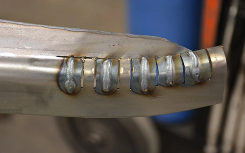
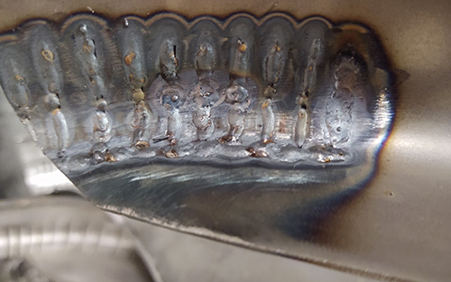
Once the tops of the relief cuts are aligned and tacked, I then weld vertical down using the MIG process, skipping a few vertical relief cuts at a time and limiting the heat in the panel. I use MIG here because the relief cuts open up when the end is formed, which creates a gap that is actually slightly larger than the 1/16-inch kerf that the cutoff wheel left behind. This gap is more easily filled with MIG welding, without the excessive heat and time it would take to TIG weld it. Remember, heat is your enemy and the least amount of heat you can use with proper penetration is what you are striving for. I have found that welding vertical down will create an adequately penetrating weld with the least amount of amperage, filler and time. It also creates the flattest weld, which takes less grinding (keep in mind that excess grinding also causes heat and shrinking).
NOTE: A sphere is geometrically the strongest shape and is generally the most resistant to heat/shrinking. A radius formed edge is a segment of a sphere, therefore it is also fairly resistant to shrinking. I am not very worried about shrinking or warping the face of the board and having to fix it because the radius-formed edge and the square-formed edge help stiffen up that face area. The top of the board is what will typically shrink because heat travels up to the flat, generally unsupported part of the running board (but the top shrink is also the most easily repaired afterward).
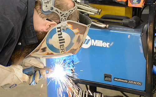
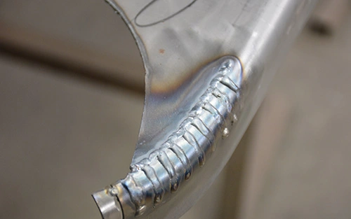
After welding the vertical relief cuts, it’s time to weld the seam that connects the radius and the top of the board. Remember, this is where the seam is intentionally the tightest. This is where I will TIG weld, which works best for tight seams. I will sometimes use a heat sink paste (Eastwood makes one I like) or an aluminum heat sink to limit heat on some welding projects, but often on these running boards I just worry about addressing the little bit of top shrink afterward with a hammer and dolly. As mentioned previously, TIG welding results in a softer weld that is more easily stretched out afterward and will be less likely to crack on the relatively flat surface of the board (which, over time, will flex and vibrate more than the radius-bent and MIG welded edge).
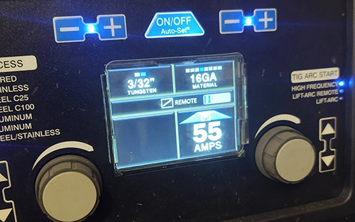
I use the Auto-Set™ technology function with a 3/32-inch tungsten. Generally around 50–60 amps is what it takes (using the 1 amp per 0.01 inch of material rule). If you want a more concentrated arc (which is better) you can use a higher degree of grind on your tungsten, such as 45 degrees instead of 20 or 30 degrees. I use 3/32 inch for everything generally because it is an adequate size for any welding thickness that I do (from 20 gauge up to 3/8 inch) so I never have to switch up my torch setup. Having a sharp tungsten is important. If you are working with dirty or oiled steel, it might mean grinding your tungsten a few times mid-project, but a sharp tungsten that creates the most contained puddle/heat possible is your friend.
Once the outside is welded, I flip the board over and switch to MIG again and weld the relief cuts previously made in the bottom square lip. Once those welds are done, I make sure the penetration is good on the backside of all the welds. If it’s not adequate penetration, I quickly switch to TIG again and fuse any seams on the backside that seem lacking, using little to no filler and just enough heat to create a puddle and fill any voids.
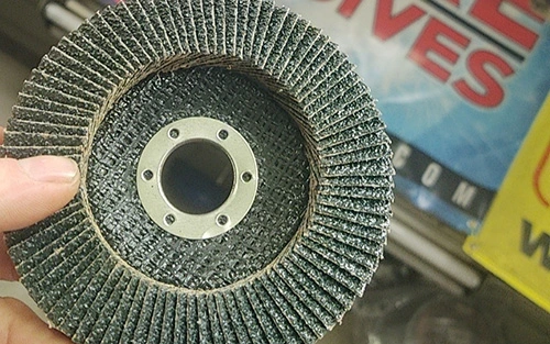
Next, I move to metal finishing. I use an Empire Abrasives 40 grit 4.5-inch flap wheel on a Milwaukee m18 grinder to knock down the high spots. What’s nice about cordless tools is they usually don’t spin as fast as corded tools, resulting in less heat from friction and limiting the potential for shrinking. When it’s all rough ground down, I switch to a 3-inch 60-grit Roloc disc on a pneumatic angle grinder to finish grinding the welds. When that’s all smooth, I hit it with an 80-grit pad on a D.A. sander.
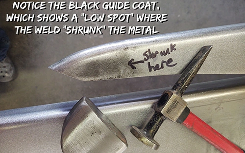
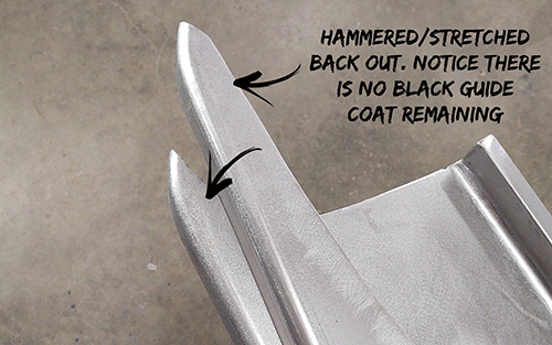
Finally, I address the small area on the top of the board that was shrunk by welding. For example purposes, I used some cheap black spray paint as a guide coat. I then hit it with a piece of sandpaper on a block. After sanding, the guide coat will remain on the low spots, showing you where you need to stretch the material out. Many metal guys use dykem or similar, but whatever you have will work. I use a simple hammer and dolly for this small stretching process. Sometimes I use my Mittler Bro’s planishing hammer on bigger areas where a hammer/dolly is less efficient. Once that’s done, the board is done and ready for paint.
I hope this article helps you to understand how your choice and execution of welding processes can affect the final outcome of your project.
Posted Feb 13, 2024
From shop layout to must-have equipment, learn how you can create your own welding space.
Learn why MIG, pulsed MIG, TIG and pulsed TIG are the ideal choices when welding sheet metal.
From shop layout to must-have equipment, learn how you can create your own welding space